|
|
|
|||||||||||
|
Choosing and installing a bilge pump system
Bilge pumps are often the most necessary and yet neglected systems aboard. The wires and connections are rarely inspected, the strum box often overlooked during the annual cleaning while the anti siphon valve may not be cleared till an actual back feed it taking place.
In this article were going to discuss types, installation, and maintenance of bilge pump systems.
Bilge pump typesBilge pumps come powered one of three ways- * electric,
They also break down in two main categories- * submersible, or
Let take a look at the different bilge pumps and what system might be best for your boat.
Diaphragm vs submersibleBilge pump manufacturers have two difficult pumping criteria to overcome. First they must maintain a dry bilge by pumping the last standing water. The bilge pump must also be able remove large quantities of water in an emergency, such as a broken through hull or collision.
Diaphragm pumps suck remotely through a hose located in the lowest point of the bilge, but they don’t pump high volumes of water and they are often not designed to be run continuously as the pump motor is not cooled by the pumped water.
Submersible pumps almost always leave an inch of standing water in the bilge, but they pump much more water and tend to run cool as they are bathed in water during operation.
Many boats have both pump types installed. One for emergencies and one to maintain a dry bilge.
How many pumps are needed on a typical boat?In the bilge pump world they say, “three is two, two is one, and one is none”. In other words when evacuating a large volume of water the pumps will be clogging, needing to be cleared. This means we can expect at least one pump to be offline at any given time.
In usage this often means two large flow submersible pumps, one electric diaphragm pump and a large volume hand pump would be considered normal for a boat heading offshore.
CapacityA good rule of thumb is a hundred gallons per hour per foot of waterline. Thus a forty foot boat would need to evacuate about 4000 gallons an hour or two 2000 gph pumps. This rule may be sufficient for any small leaks, but for a serious leak like a broken through hull or collision we must look to large capacity externally driven bilge pumps.
For example, a few years back I was aboard a sinking boat. The electric bilge pumps and the manual pumps were employed but the inside water level continued to climb.
Over the next hour we were given two petrol driven emergency pumps. The water level stopped climbing and only when a third petrol pump was employed did the water level lower sufficiently to find the source of the leak.
Swimming through the bilge in my wetsuit I found a hole near the keel. It was so small I could barely fit my hand through yet three petrol pumps and the boats internal pumps could barely keep up with it.
The lesson learned is pumps are very inefficient at moving water, while holes in the hull are very efficient at allowing water.
For example a 75mm hole 500mm below the water line will allow about a thousand liters of water into the boat PER MINUTE. To deal with a real emergency the boat needs a crash pump.
High capacity crash pumpRemoving large amounts of water quickly such as after a collision, a sprung plank, or maybe when a rust hole opens on a steel boat is beyond the ability of most bilge pump systems.
Boats facing these threats turn toward-
* Hydraulic driven pumps
Hydraulic bilge pumpsMany boats have a hydraulic system installed for running the windlass, winches, or fishing gear. For these boats a simple solution is to purchase a direct coupled hydraulic bilge pump. These pumps can move large quantities of water, often in the range of 400 lts per minute.
Hydraulic pumps come in two styles * Water
Trash pumps move slightly less water, but can accept larger chunks of debris. These are normally a better solution for boats that may have dirty bilges during a flooding.
Prop Shaft driven pumpsA clever solution for removing a large quantity of water is the use of a prop shaft driven pump. These pumps are mounted on the prop shaft and are turning any time the gearbox is engaged. They are designed to run dry functioning as a bilge blower in normal operation. The main advantage is the boat operator does not need to realize the bilge is flooding before action is taken automatically. The operator continues to motor toward a safe haven while the submersible propeller shaft driven pump maintains a safe water level.
The claimed flow rates are amazing at over 1600 lts per minute. The cost is reasonable at about $900NZD. See www.tongacharter.com/bilge.htm for more details.
Pump efficiencyBilge pumps have a flow rate printed on the side, but often the numbers seem optimistic. One of the reasons for this disparity is flowing water tends to swirl, and form back eddies around any obstructions such as imperfections in the interior surface of the hose. Another cause of reduction in water flow is the slight drag formed by the strum box, or filter on the suction end of the hose. With this in mind let’s look at how we can make our bilge pump system more efficient.
HoseBilge pump hose interior should be smooth bore and resist collapsing if suction is formed. Often we use see head hose used as bilge hose. This is a good, but a slightly more expensive solution to preventing back eddies along the surfaces of the hose walls.
Tip- The concertina type hose sometimes used in inexpensive applications is the worst for causing multiple eddies in bilge hose.
Thin walled hose connectorsBilge hose sections will need to be connected at points along the run. The joining coupling should be thin walled to prevent the added resistance of pumping past a smaller diameter. The hard corners of the hose insert can also from form back eddies causing more flow restriction.
Clogging pumpsBilge pumps tend to be robust, dependable, and last near forever till they clog. Clogging causes two problems for the pump. First the pump never clears the bilge so it continues to run dry till it burns up. Second some of the clog may work its way to the impeller causing extra drag that will quickly ruin the motor.
The main reason bilge pumps clog is sloshing water picking up debris in the bilge and washing it over the pump. Cigarette wrappers, plastic bags, and labels from cans have all fouled their share of bilge pumps.
MountingSubmersible pumps must be securely fastened to the hull to prevent sloshing water from dislodging the pump and causing it to suck air. Most pumps allow simple snap connection of the strum that can be screwed to the hull, and the pump merely set into position. If a clog occurs the pump can be removed with one hand and the strum cleared of debris.
Tip- Be sure to dip the screws into a tube of sealant such as 5200 or silicone before screwing into place. This will help the submerged screws from rotting the mounting board.
Bilge pump hose mountingIn general, the first rule of bilge hose is “the straighter and shorter the better”.
The bilge pump hose should be secured to the boat, but the last couple meters near the pump should be left to “float” so when a clog occurs and the pump is lifted free from the bilge the hose does not restrict pump movement.
The pump hose routing should form a loop well above the waterline. If the bilge outlet is above the waterline then no anti siphon valve is needed, but if the bilge through hull is below the water line (as is often the case in older boats) then an anti siphon loop is a must.
The hose routing should stay on center line as much as possible so when the boat is on a heel the hose profile is not under the waterline. This could be a problem if a bilge hose were routed up the side of the hull, looped and routed to a through hull directly above the water level. When the boat heals the anti siphon loop and the through hull would both be under water. It only takes one use of the bilge pump to fill the hose and start a back siphon.
Through hullThe through hull should exit above the water line. Some boats used to be built with the through hull bellow the water line in an attempt to prevent the dirty streak left over from the last drops of bilge water, but the risk of back feeding water has prevented this technique.
Inside the hull the hose should rise to a level above the exit through hull, loop over and be dropping water into the through hull. This causes the water to accelerate due to gravity and thus the column of water becomes thinner making it easier to pass the more narrow bilge outlet.
This accelerated water flow allows the connection of a thick walled through hull to the bilge hose without a large loss of flow. Still if possible the through hull should be up-sized over the bilge hose diameter thus the water flow will be increased.
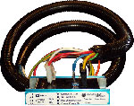
Bilge pump wire runsBilge pump wires are vulnerable to corrosion, snagging on bilge items, being ripped free, and water running down the wires that contaminate and eventually ruin the wire connections.
For this reason we want the pump wires to quickly rise away from the pump and corrosive bilge water. If the bilge pump hose is able to make this same route then it’s simply a matter of securing the wires to the bilge hose so they can’t be ripped free from the hose.
If the pump wires and pump hose run in different directions then the wires should be protected with external covering such as split conduit.
Waterproof wire connectionsThe best water proof connections are made with double heat shrink. First a crimp connector with built in heat shrink, followed by a second heat shrink covering. Strip the wire insulation, fold the copper wire in half to add thickness inside the crimp connector, dip the wire end in silicone grease, insert the wire end into a heat shrink crimp connector and crimp with a ratcheting type crimper that does not pierce the heat shrink. The heat shrink is shrunk using a hot air gun. The second layer of heat shrink covers both positive and negative wire connections. Slide both connectors into a larger tube of high quality heat shrink and heat. The ends of the covering heat shrink are sealed by a gentle squeeze with a large pair of linemen pliers that flattens and seals the heat shrink ends.
Tip- Check rotation. Most bilge pumps will work if wired in reverse polarity, just not very efficiently. To check rotation flip the bilge pump upside down and watch the impeller spin to verify correct rotation.
Bilge pump breaker optionsA continual debate among marine electricians is how to wire the bilge pump to the boat battery system. One school of thought says a simple breaker off the main panel to the auto/manual switch is sufficient. The disadvantage is when the battery switch is turned off the bilge pump is disabled.
The next option is to wire in a second emergency panel separate from the main panel that is not connected through the battery switch. This is better and has become the standard of the industry, but involves buying and installing a complete second electrical panel.
The last group argues that too many boats have sunk at the marina due to a simple breaker, or wire connection that got hot or corroded and eventually failed causing interior water damage to the vessel. The solution they argue is to wire the main bilge pump directly to the battery through large, pre tinned wires. They claim the benefits of a bullet proof bilge pump electrical supply outweigh the possibility of a wire overheating or a bilge pump fire through an unprotected circuit.
Amazingly sailboats flounder at sea more often than launches even though they are outnumbered 8:1. When a launch sinks it often goes down by the bow meaning the stern may be lifted causing the water to run toward the bow leaving the stern bilge pumps high and dry while the last of the bilge floods.
Float switchesUndoubtedly the most undependable aspect of a bilge pump is the float switch. It’s susceptible to corrosion, water intrusion, sticking, capture by other bilge debris, sloshing, and even the occasional crushing by a heavy foot.
Today we have two competing styles of bilge pump switches. The all electronic water sensing type and the traditional float that flops up activating an internal switch. Variations include float switches that have a built in covering cage or the all enclosed tube with internal float.
Tip- To test if a continuity activated switch is working lay two finger tips over the sense pads. The pump should jump to life.
One advantage of the resistance activated bilge switch is it should not turn on in the presence of diesel or oil as both are not conductive. The disadvantage is they can be fouled by sludge formed from oil in the bilge coating the sense pads.
Sludge is formed when oil in bilge water adheres to surfaces and then collects dirt. Ultimately it becomes a tar-like substance that will prevent the float switch from moving. Clean bilges are the solution to preventing sludge.
Wire tie tailsNothing can kill a bilge pump like old cut off wire tie tails that make their way into the bilge. They are just the right shape to fit past the standard strum on the bottom of the pump and the tail can cause just enough drag on the impeller to reduce flow and eventually ruin the pump. If the wire tie tail is sucked into a hose it will travel till it jams in a corner eventually catching more bits till it forms a clog, or it may travel all the way to the pump where it will jam a check valve.
The solution is to catch and track down every wire tie tail that has been cut off. Each lost tail is a possible bilge pump clog.
Note- Aluminum boats should never use mercury operated bilge switches. In the unlikely event the housing was to break releasing the mercury into the bilge the aluminum is dissolved at a rate of billions to one. In other words the mercury will dissolve a hole in the aluminum hull in just weeks.
Comparing bilge pump brandsThere are many bilge pump brands and models all rated differently. To make sense of the multiple options we asked Stuart Hay of Lusty and Blundell who provides a simple rule of thumb.
"Due to the range of methods used by different manufacturers to
rate
Water tight bulkheadsMany boats have a series of water tight bulkheads providing separate flotation areas through out the boat. Each section should have at lease one bilge pump, and the complete boat is normally connected through a series of large suction pipes run to a crash pump. The main advantage is during an emergency it is much more difficult for the boat to sink.
The main disadvantage is each section of the bilge holds a small amount of water keeping the bilges wet, thus smelly and moldy. Multiple bulkheads also cost more during the construction phase and to move through the boat often the crew must climb through a series of deck hatches
Hand operated back upThe electric bilge pump system must be backed up with a large flow manually operated bilge pump. The suction for the emergency pump should be low in the bilge and have a strum installed to filter the incoming water.
Tip- The suction end of the hose can have a line attached so it’s easy to lift and clear when clogged.
Location of manual pumpThe general school of thought is the manual pump should be located so it can be pumped from the helm. This allows the last crew member to pump, and steer the sinking boat into port while clearing the bilge.
The main disadvantage of this system is the pump is often located at deck level in an inaccessible location. Long suction lines are notoriously inefficient at moving water.
Many cruising boats opt for a pump located inside where- * The operator is safe from the outside weather
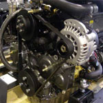
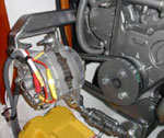
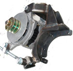
Yachtwork- In answer to last month’s question as to why the engine oil heat exchanger is cooled by the engine fresh water while the gearbox is cooled by the raw water. The answer is the temperature differences. A gearbox might run at 50c so that is close to the sea water temperature, while engine oil may run at 100c so being cooled by engine fresh water at 80c is also close in temperature. This prevents cold oil contacting hot metal causing it to harden and become brittle.
|
||||||||||
| © Team Yachtwork 2007 | |||||||||||